The Official Publication of the Bucks-Mont Astronomical Association, Inc
____________________________________________________________________________________________________________________________________
© 2001 BMAA, Inc
News release
Winter Star Party or TVASEC South (Shifting Sands Observatory)
-by Allen Rodriguez
|
Hi, everyone! The Shifting Sands Observatories' Lab has been completed. The Lab has turned into a nice small cottage with room for fellow sky watchers. The observatory is an 18' x 24' rolling roof pleasure. Only takes a minute or two to open or close up. It houses a 14" Celestron, 8" LX200 and stuff. Very comfortable with great night sky views. Also a bit warmer than PA in February. The 800 square foot Lab has one bed room, a bunk room, a recreation/computer room, a living room with a dining area, a kitchen, a bath and of course the necessary laundry and dryer closet. It's closest town is Chiefland seven miles to the north. I usually drive straight through as it is only 1020 miles from my home in Warminster. The Chiefland Astronomy Village has wonderful villagers; all astro nuts. The Village is composed of some twenty, five acre lots with homes and observatories on about half to them. My neighbor to my west is Cliff with a 24'x24'observatory housing the new Astroworks 18" f/2.8 Centurion with a water cooled SBIG ST-7 - fabulous images. My neighbor Jack, down the road |
uses a 16" LX200 to make images for Meade's advertising pages and has a B&B for those who would like to really learn how to do CCD imaging (JackNewton.com), across the street is Bob who hunts asteroids with a 12" LX200 housed in a beautiful new roll off observatory. Just down the road is Andy who has an Astronomy Magazine front page shot of Hale-Bopp and next to him is the home of Tectron dobsonians, Tom, the editor of Amateur Astronomy and a new 36" dob. To the north of me and to the south of me are new observatories in construction. Truly a heavenly place!. If you are not going to the Florida Keys for the Winter Star Party and you feel you would love a FFV (February Florida Vacation) then you are invited, as a BMAA member, on a first come basis, to join me at the Shifting Sands Facility. (See photos of Shifting Sands here.) |
Allen Rodriguez
Chiefland, FL
* * * * * * *
- BMAA member, and past-president, Allen Rodriguez divides his year between three homes in PA and FL. [ -ed]
___________________________________________________________________________________________________________
2001 MEMBERSHIP DUES ARE DUE NOW!
Astronomy 101 is an informal Q & A session before each General Meeting at 7:30p,
The next BMAA General Meeting is scheduled for Wednesday, January 3 at 8:00p
BMAA MESSAGELINE - 215/579-9973
___________________________________________________________________________________________________________
The CONSTELLATION is the official publication of the Bucks-Mont Astronomical Association, Inc, a 501(c)3 non-profit organization incorporated in the Commonwealth of Pennsylvania and exists for the exchange of ideas, news, information and publicity among the BMAA membership, as well as the amateur astronomy community at large. The views expressed are not necessarily those of BMAA, but of the contributors and are edited to fit within the format and confines of the publication. Unsolicited articles relevant to astronomy are welcomed and may be submitted to the Editor.
Reprints of articles, or complete issues of the CONSTELLATION, are available by contacting the Editor at the address listed below, and portions may be reproduced without permission, provided explicit acknowledgement is made and a copy of that publication is sent to the Editor. The contents of this publication, and its format (published hard copy or electronic) are copyright © 2001 BMAA, Inc.
In an effort to transmit the CONSTELLATION electronically to the membership of BMAA, please provide a current e-dress to the Editor. Abbreviated issues are available on the web site, but complete editions will be e-mailed to members in good standing.
Submission deadline for articles is the 15th of the month prior to publication.
Bucks-Mont Astronomical Association, Inc
(Tentative)
StarWatch Chairman: Ed Radomski - 215/822-8312, ejrado@prodigy.net
Information Line - 215/579-9973
___________________________________________________________________________________________________________
2001 BMAA Officers
President - Ed Murray, 215/493-2843 edward12@erols.com
Vice President - Antoine Pharamond, 215/412-9291 apharamond@adelphia.net
Treasurer - Ed Radomski, 215/822-8312 ejrado@prodigy.net
Secretary - Ken Wieland, 215/362-7228 wieland7@netreach.net
___________________________________________________________________________________________________________
FOR SALE: Meade ETX-90EC Astroscope w/Barlow, prisms, electric focuser, autostar, tripods, case and reference books. New June 1999 - never used. $1,000.
Contact Bob Luof, POBx 116, Danboro PA 18916 - 215/766-9094.
It slices, it dices, its Ronchi !
- by John C Deitz
Three tests are applicable to field testing your complete telescope under the stars: the knife edge, the Ronchi, and the star test. Each has particular strengths and weaknesses, and vary in sensitivity, ease of interpretation, tolerance to atmospheric disturbance and collimation error.
The knife edge test is easily applied in examination of "tube currents" and more distant atmospheric disturbances (November CONSTELLATION). More subtle are the shadows encountered with less than perfect optics (December CONSTELLATION). In this issue of CONSTELLATION we will explore another easily applied test, the Ronchi test.
The apparatus is simple (November). Replace the knife edge with a piece of film with multiple fine lines having spaces the same as the line width. Greater number of lines allow for increased sensitivity, BUT with line spacing above 125 lines/mm diffraction becomes a bother. Gratings of 120-150 are suitable. Two inch by two inch pieces are available from Willman-Bell for ab0ut four dollars per grating, while a set of three (80,100, and 150 line) can be purchased from Orion for $7.00. A 1/2 inch by 1/2 in. piece is more than you need, mounted inside the file can just in front of the hole punched in the cap. A washer can conveniently be glued in place, centered on the hole, and the Ronchi grating glued in turn to the washer. Now all that is needed is a clear night with moderately good to good seeing.
Under most conditions this test is NOT particularly sensitive for an optical system that departs SMOOTHLY from perfection. The sensitivity of the test depends upon how fine the grating is, the mirror diameter, the focal length and the distance from the point of best focus. HOWEVER, it is easy to perform, tolerates moving air a little better than the knife edge test, and shows short period defects better than the knife edge test. Poor edge (turned up or down), roughness, and astigmatism are more easily detected than with the knife edge test.
Here's how to perform the test. Center on a 2 or third magnitude star. Remove the eyepiece and replace with the Ronchi test eyepiece. With your eye close to the test eyepiece you will see multiple lines superimposed on the bright spot representing the objective. Turn the eyepiece until the lines are approximately at right angles to the motion of the star as seen without the drive on (this is not very critical and is suggested only as an aid to this discussion). Now watch what happens as you slowly push the eyepiece into the focuser tube (or use the rack and pinion). If the number of lines DECREASES you are outside focus and moving toward focus. As you continue moving inward a single line will fill the view and then the numbers of lines will start to INCREASE- you are now INSIDE focus. It is VERY important for this test to know you are inside or outside focus when you interpret the pattern! The patterns with this article assume you are OUTSIDE focus (that is, moving the grating inward results in FEWER lines).
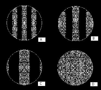
The test has greater sensitivity with smaller number of lines showing. Any departure from a straight line indicates image aberration. The sensitivity increases as the number of lines decreases. That is, as you approach closer and closer to the focus (while remaining outside the focus for this article) the more pronounced the departure from a straight line. However, you might run the risk of completely hiding the "bad spot" behind a single band. For smooth departures from perfection the curves can be very subtle. In Illustration 1, we see a change in the number of lines as we move from "A", outside of focus, to "B" a little closer to focus. With a little further movement to "C" we are very close to focus indeed. Image at "D" is at the focus. The pattern is repeated on the other side of focus. Look closely and you can see a departure from "straightness" that looks more evident in going from A to C. This represents 1/4wave departure from perfection for a common instrument! This is subtle, and even harder to see with atmospheric disturbance. Moving the scope back and forth across the star can cause these shallow curves to appear more distinct. That's why I suggested aligning the grating along a north-south line. Turning off the drive and watching the image drift rapidly over the lines will accent the change in shape. Smooth variations from the ideal figure are hard to see with this test, but turned edge, zonal defects, astigmatism and roughness can be easy to spot. Let's take a look at specific examples.
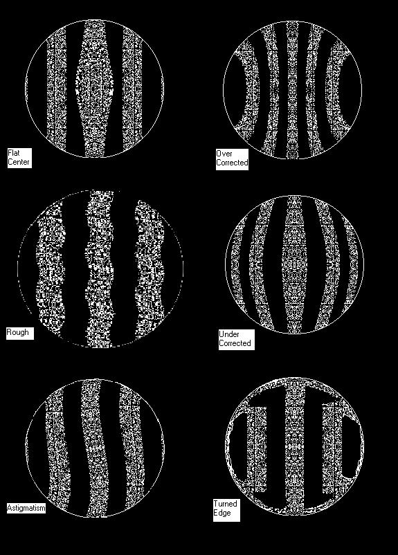
In Illustration 2 we see an example of a zonal defect, in this case a flat center to the objective. It looks like a hill, with the unaffected areas maintaining straight lines. Such a defect would largely be covered by the secondary shadow if seen in a Newtonian. Next we see an example of overcorrected optics. With a little imagination this looks like what it is- a "too deep" surface! Under this image is an example of undercorrection. Just as the name sounds this is too much of a "hill" and so causes the lines nearer the edge to curve outward. Right beside this is an example of large scale surface roughness. This can be hard to spot with other tests but is quick and easy with the Ronchi test.
Astigmatism (Illustration 2) is also better seen with the Ronchi test, but will rarely be encountered. I have seen this on one occasion of a Newtonian that, with evaluation of the secondary, proved to have 2.5 waves departure from flat! It may be seen with "pinched optics" in too tight a cell, or in a refractor if airspaced elements are off- center. If the grating is tilted in the light path the appearance of astigmatism will result. If the defects follows the changing orientation of the eyepiece as it is rotated then the "defect" is an artifact of a tilted grating. On the other hand if it reaches a "peak", lessens, and returns to a peak after 180 degree motion it is astigmatism in the optical system.
A turned edge (Illustration 2) is more likely to be seen in the Newtonian. The hall mark are straight lines until the edge of the mirror is encountered where the departure is sudden and very evident. This is a common defect and should be corrected by a mask over the outer edge of the mirror.
If you encounter some of the defects, make a note of them. Take your time and watch them. Some will come and go with changes in temperature. Some may be a result of a "pinched" (stressed) primary or secondary. Local defects around the secondary on a compound scope may be the result of temperature variation or the weight of the secondary. Change the orientation of the scope and see what happens. If you suspect astigmatism then rotate the primary and see if it follows. Keep in mind that defects toward the center of the optical system contribute to image formation to less a degree than those at the edge.
|
|
Illustration 1 : Progressing from "A" to "D" as the Ronchi eyepiece is moved inward. Gratings with greater numbers of lines/mm, placed closer to focus (showing fewer lines) are more sensitive and show more departure from straight for a given defect. Look closely at this example to see a departure that, under these conditions, represents 1/4 wave! Keep in mind, shorter more rapid changes in slope are easier to see. Bad edge, zonal defects, roughness and astigmatism often display well. These images are modified from the output of Mel Bartel's program (The Matching Ronchi Test) for testing at the center of curvature. Be warned: if you download and use his program for mirror evaluation, the limits given are for 1/2 wave NOT the stated 1/4 wave. For Windows try John Upton's freeware, a user-friendly program for evaluation at the center of curvature. |
Illustration 2: The appearance of the Ronchi test for a number of common defects. The patterns are those seen OUTSIDE focus! If, on moving the rack and pinion inward, fewer lines are seen then you are OUTSIDE and moving toward focus. The fewer the lines the more sensitive the test. Fewer lines can be had by using a grating with a greater number of lines/mm. AND placing the grating close to focus. Also, motion of the star across the grating helps to visualize the overall shape of the objective.
* * * * * * *
BMAA member John C Deitz provides technical articles and can be reached at
johncdeitz@cs.com -[ -ed]___________________________________________________________________________________________________________
Observing Tips
Stability and Smoothness in Mounts
(The turn of the century for real this time.)
- by Bernie Kosher
The weather has been most uncooperative. I had been writing articles on observing the Messier objects, but find I am unable to follow my own target of at least one per observing session. Unfortunately, the only clear skies have been moonlit. I have been doing planetary and lunar, but even there the turbulence has been awful.
Since there's no observing going on, I'd like to talk about a subject that's important to me; stability and smoothness in the mounting.
Many of today's mounts are the Dobsonian type, certainly cheap and easy to build. In most cases the mount is as stable as one could ask, but there are frequently balancing problems. Sometimes the mount is just plain under-designed. Sometimes the materials used are the cheapest possible and perform in ratio.
Throughout the section on Dobs, I am assuming a balanced scope, although this in itself is a big problem. The first step before any of the following should be to get the scope balanced for some favorite eyepiece, finder and Telrad combination thus keeping it from 'coasting' in any orientation. This is easier said than done. The scope is fairly easy to balance for any one orientation, but for all it is much more troublesome. So do this over the wintertime and save yourself tons of observing aggravation come the nice weather.
If your mount requires a much harder tug to get it started than to keep it moving, you should search out the culprit. If the scope drifts backward after moving it, this drift should be eliminated. Stiffening the mount and adding the correct bearing surfaces will most likely take care of this. Hard 'starting force of friction' and jerkiness are caused by A) warping B) binding glides C) mispositioned glides D) gummy buildup in the glides E) unbalanced condition F) poor choice of sliding surface material G) lack of rigidity in the mount, and undoubtedly other reasons.
Take a basic dob mount from about any of the low cost scope manufacturers and you can find ways to improve it. Several examples of problems I have seen and some of the repairs and suggestions follow.
The worst examples I have seen are the type made of fiberboard using no adhesive, just screws. As everyone should know, these woods are not made to hold screws driven in edgewise, especially parts are under stress. I highly recommend you take the time to dissemble the unit, add a good adhesive to the joining points, and then screw them back together. Seal the wood with several nicely applied layers of paint. If the wood is natural, stain first, then use urethane to seal.
Polyurethane paints feel very rough with just one coat. Sand lightly between coats until frosty, then recoat. Three coats will do a very nice job.
If your mount is very shaky, add strips along the uprights, well glued and screwed. The effect may be cosmetically unnerving, but will improve the scope's performance.
If the upright boards do not have a brace running partway from the baseboard upward, add one, well glued and screwed. Even if the mount has a backboard this will help.
I recommend doubling the thickness of the groundboard, or taking an even more effective, but more difficult, route, i.e. make a web of 2" wide 3/4" plywood strips for the bottom of the base. Cutting the web as a triangle is not difficult, especially if one has access to a radial arm saw. Make the triangle the full width of the base. This will stiffen the groundboard considerably. Do not make the feet too tall, or there will be a risk of the scope tipping over if pushed sideways. Part of the binding problem I see in these mounts is caused by the groundboard warping on uneven ground, even if the base uses feet. All of these mounts should have feet at least two inches high to get it above uneven ground and establish a wide three point support instead of following the ground on which it is standing. Perhaps better still would be a hexagonal web, using the same three feet already mentioned.
These feet should be directly below the glides, or at least on the same radial line and close to the glides As an aside, it escapes me why the glides are on the underside of the baseboard and not the upper side of the groundboard. Since the weight of the scope is born by the glides, why not be sure the weight is carried through to the feet? It seems to me this is better than the glides being, at one point, halfway between supports.
The azimuth glides (Teflon recommended, if yours are plastic go to the store and buy a set of Teflon furniture glides and replace the pieces of junk) should be well out toward the perimeter. I would think at the 70% of radius zone. Perhaps one of our mechanical engineering people will give thoughts on this. Mr. Post, perhaps?
While on the altitude area. If the mount uses the rigid and well attached trunions as tube mounts all is probably well. If they are the thin, hollow plastic type, these could well be the cause of much binding and 'driftback' due to flexure and distortion. I would like to see them replaced with disks of wood or whatever. Even thick PVC sections would be more rigid than some of the trunnions I've seen.
Naturally, the trunnions must be located at the correct pivot points on both sides, else the tube will not rotate parallel to the uprights.
If the mount uses a central support at the pivot it must be the same thickness as the other pivots. If the baseboard and groundboard are not perfectly parallel the boards will distort to find a 3-point support of it's own and not the points you want.
The altitude glides should also be Teflon. If yours are not, replace them.
Minimum drag with minimum rock on the alt is achieved with the glides 52 degrees from the center line of the pivot ring. Phrased differently, they should be 104degrees apart. However, this will probably leave them with too little drag. Experiment is the only solution to finding a happy compromise. Spacing them wider will increase drag, also binding. Closer together is not recommended, as the scope will tend to lift off one or the other when moved.
My personal favorite for the sliding surfaces is pebble grained Ebony Star. Others probably work just as well. The combination of pebble and Teflon seems to provide just enough drag to hold the scope from tilting, but still limit the starting force of friction.
The facing points of the glides can well be grooved to allow a reservoir for gunk. Most machine applications using pressure plate clutches have them grooved for this reason. Smooth surfaced clutch plates quickly bind due to a buildup of foreign material on the surface. Cutting grooves gives this gunk a place to go. Grooves can be cut easily with a thin bladed saw. Using pebble grained Formica helps here and probably renders cutting grooves unnecessary.
The central pivot requires some thought. If this is a simple bolt with nut it will eventually ream out the wood around it. About the
best remedy is a pair of Oilite bushings, available from a Sears Hardware store, with a bore the same size as the bolt. You will have to enlarge the hole in the wood to accept the bushings and then put small screws around the flange to hold them in place. This will greatly improve the smoothness and lengthen the life to about forever.
There are other ways of doing things to make a sticky mount better, and improving the stability. A good dob should quit shimmying almost immediately after a sharp rap to the tube. If it doesn't then you can make it better.
Notes on improving the equatorial somewhere in the future.
* * * * * * *
BMAA member Bernie Kosher provides 'Tips' monthly and can be reached at
bkhere@optonline.net [ -ed]